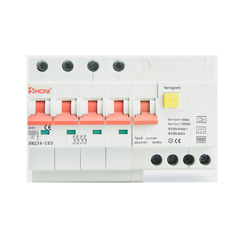
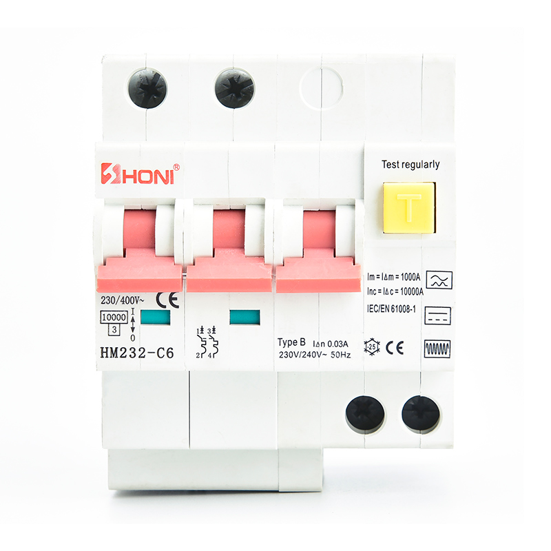
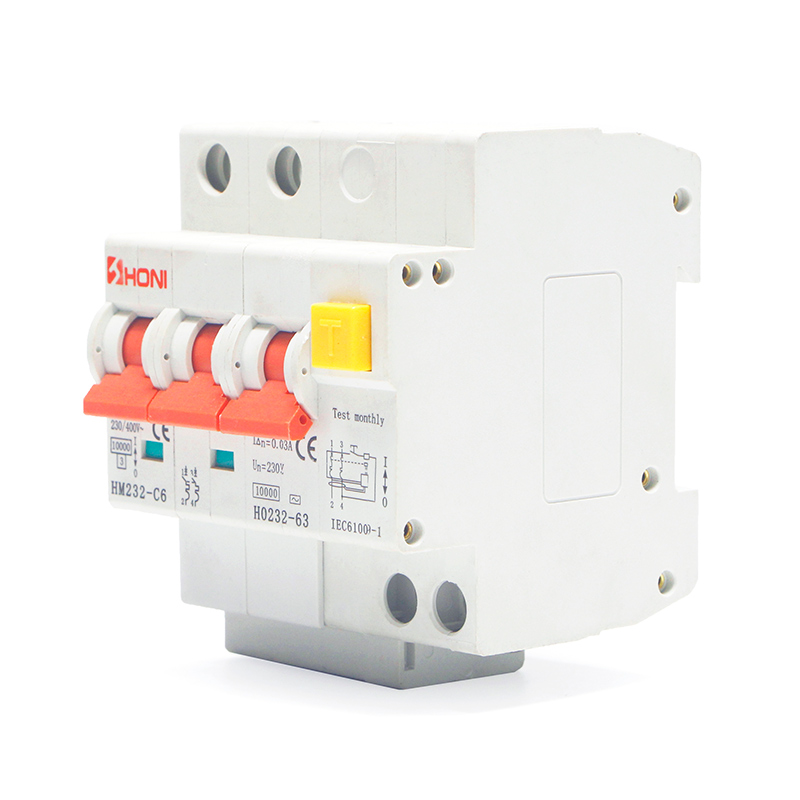
HM232-125/HM234-125 Residual Current Circuit Breaker With Over-Current Protection (RCBO)

By combination with miniature circuit breaker => RCBO-Unit (MCCB) Add-on residual current unit (screw connection) for 80 or 125 A (2-pole and 4-pole) • High flfl exibility and ease of installation thanks to variable wiring (400 mm flfl exible connection wires 2p = 2 units, 4p = 4 units included in the set) • Free selection of main power supply • Auxiliary switch 1 NO included as standard in all FBHmV versions • Permits combinations with a variety of characteristics thanks to the differentrated currents and characteristics of the miniature circuit breakers AZ which can be connected

Products Details

By combination with miniature circuit breaker => RCBO-Unit (MCCB) Add-on residual current unit (screw connection) for 80 or 125 A (2-pole and 4-pole) • High flfl exibility and ease of installation thanks to variable wiring (400 mm flfl exible connection wires 2p = 2 units, 4p = 4 units included in the set) • Free selection of main power supply • Auxiliary switch 1 NO included as standard in all FBHmV versions • Permits combinations with a variety of characteristics thanks to the different rated currents and characteristics of the miniature circuit breakers AZ which can be connected • For trade and industry applications • For subsequent mounting onto 2, 3, 3+N and 4-pole-miniature circuit breakers • Toggle (serves as switch position- and tripping indicator) • The screw connection to the device can be unscrewed at any time. Consequently, in case of modififi cations of the systems to be protected, the installation can be adapted to new requirements at any time. • The test key “T” must be pressed every 6 months. The system operator must be informed of this obligation and his responsibility in a way that can be proven. Under special conditions (e.g. damp ly and/or dusty environments, environments with polluting and/or corroding conditions, environments with large temperature flfl uctuations, installations with a risk of overvoltages due to switching of equipment and/or atmospheric discharges, portable equipment ...), it’s recommended to test in monthly intervals. • Pressing the test key “T” serves the only purpose of function testing the residual current device (RCD). This test does not make earthing resistance measurement (RE), or proper checking of the earth conductor condition redundant, which must be performed separately
Electrical
Design according toCurrent test marks as printed onto the device IEC/EN 61009
Tripping Instantaneous 250A (8/20μs), surgecurrent-proof
Rated voltage                      Un 240/415V AC
Voltage range test circuit 2-poles 4-poles, 30mA 4-poles, 100, 300, 500,   196-264 V~ 196-264 V~ 196-456 V~
Rated frequency 50 Hz
Rated tripping current               I△n 30, 300, 500, 1000 mA
Rated non-tripping current           I△no 0.5 I△n
Sensitivity AC and pulsating DC
Rated current                       In 80, 125 A
Rated short circuit breaking capacity   Ics 10kA
Rated short circuit capacity           Icn 7.5kA
Rated impulse withstand voltage      Uimp 4 kV (1.2/50μs)
Endurance electrical components 80A 125A mechanical components 80A 125A³     ≥1,500 operating cycles ≥ 1,000 operating cycles   ≥ 10,000 operating cycles ≥ 8,000 operating cycles
Electrical Auxiliary Contact
Rated voltage               Ue 250 V AC
Rated operational current     Ie 16 A AC
Mechanical
Frame size 45 mm
Device height 90 mm
Device width 95 mm (5,5TE)
Depth of central body 60 mm
Mounting screwed onto AZ 2-, 3-, 4-poles;
Degree of protection switch IP20
Degree of protection, built-in IP40
Upper and lower terminals lift terminals
Terminal protection fifinger and hand touch safe
Terminal capacity main conductor auxiliary switch   2.5 - 50 mm² 1 - 25 mm²
Operation temperature -25°C to +40°C
Storage- and transport temperatureResistance to climatic conditions -35°C to +60°Cacc. to IEC 68-2 (25..55°C / -90..95% RH)

Contact us

Please feel free to give your inquiry in the form below We will reply you in 24 hours